Controlled Point
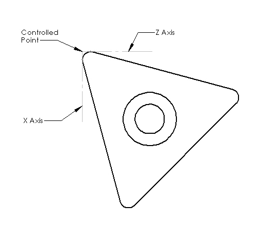
The Controlled Point is a point that is defined by the X offset, Z offset and the tool orientation. The path followed without tool radius compensation is the controlled point.
On a lathe when cutting along the Z and X axes doing facing and turning operations where the tool path is parallel to the axis tool radius compensation is not needed because the controlled point is tangent to the radius of the tool tip. Notice in the following figure the controlled point is not the edge of tool radius but rather a point that is formed by two perpendicular lines that are tangent to the radius and on the side defined by the tool orientation.
Tool Orientation
This topic is covered well in the LinuxCNC user manual so I’ll just highlight some things here.
-
The path when using Tool Diameter Compensation affected by Tool Orientation
-
Insert Nose Radius must be doubled to diameter in the tool table.
Tool Radius Compensation
Normal lathes have the imaginary Y axis positive end on the floor so when looking from the top tool radius compensation direction is reversed.
A lead in move that is greater than the tool radius is required when starting a series of moves using tool radius compensation.
The path must not have any inside moves that are less than the tool radius.
Compensation Example
In the following example code I will show you the path taken with compensation turned on and the tool path with no compensation.
Tool 2 in the tool table is set to the following in this example.
DIAM = 0.125
FRONT = 85
BACK = 25
ORIEN = 2
G7 G20 G18 G40 G49 G64 P0.005 G80 G90
T2 M6 G43 (tool change on the sim is at X2.000 Z0.9488)
G42 (left of programmed path for normal lathes)
G0 X1.000 Z0.250
G1 Z0.000 F2
X1.125 Z-0.125
X2.0
G40 (turn compensation off)
G0 X1.000 Z0.250
G1 Z0.000 F2
X1.125 Z-0.125
X2.0
M2 (end of file)
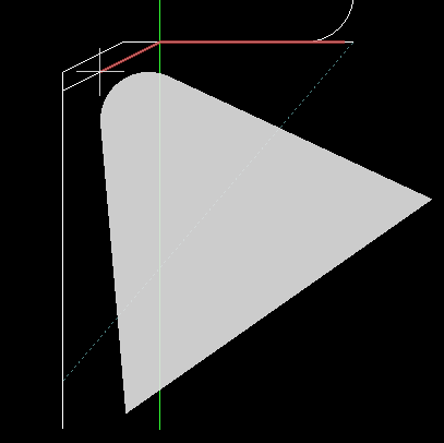
In the following image you can see the controlled point shown by the white cross does not follow the desired outline of the part but is beyond the part enough so the tool nose radius will follow the outline desired. Also note that this is tool position 2 so the first and last parts of the move are not offset.
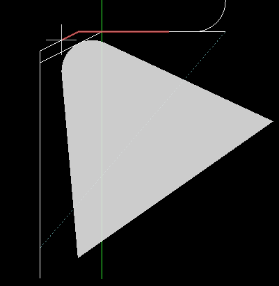
In the following image you can see the path taken with no compensation and see how the tool tip does not follow the desired path but the controlled point does. The first and last part of the move will be correct but the chamfer will not be correct.